.png)

Brayton cycle - Gas turbine cycle
- rameez badhurshah
- Oct 29, 2021
- 6 min read
We are back with yet another cycle and this time it's the Brayton cycle, the most efficient cycle. What's more - it is the cycle on which the gas turbines work. The origin of this cycle dates back to the 1870s where it was designed for reciprocating engines. But owing to its excellent characteristics, today Brayton cycle is only used in the rotatory type gas turbines where compression and expansion both take place. These gas turbines are used either in power plants to drive large turbines or in jet engines to propel the aircraft. So, let's fasten our seat belts and take off ourselves to learn more about this cycle.
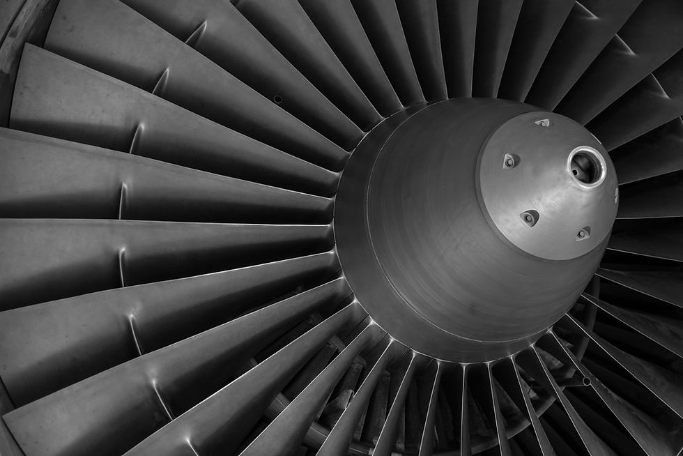
Table of Contents
Introduction
Open and closed Brayton cycle
The efficiency of the Brayton cycle
Brayton cycle - Increasing the net work
Jet propulsion cycle
History
Summary
References
Introduction
In the last series of posts, we focussed on the Carnot engine cycle and then the Otto and Diesel cycle. We understood the importance of these cycles and how these cycles power our vehicles for our daily journey. Quite a few times though (before the pandemic and now that things are turning back to normal), we surely use the fastest mode of transport - aircraft for our long-distance or overseas journey. And I am sure, the first time you might have seen the engine of these aircraft, you would have been amazed by the size and robustness of it. How interesting it then would be to read and learn more about these engines or the cycle that powers these engines.
Open and closed Brayton cycle
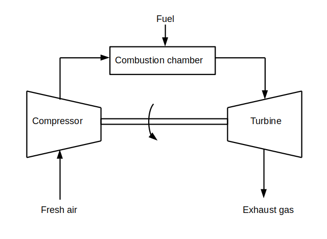
In most cases, the gas turbines work on an open cycle. For every cycle, fresh air enters the compressor at the surrounding ambient conditions and leaves at high temperatures and pressure. This high-pressure air then enters the combustion chamber where the combustion of fuel at constant pressure takes place. The gases at the end of the combustion chamber leave at high temperature and make an impact on the blades of the turbine, thereby rotating the turbine shaft and thus producing the power. Further, these exhaust gases are released into the atmosphere. As no recirculation of gases takes place, the entire process is termed an open cycle. A schematic is shown below to acknowledge the operation of the open cycle.
The same open cycle of the gas turbine described above can be designed as a closed cycle using air-standard assumptions. For the closed cycle, the compression, as well as the expansion processes, remain the same. The combustion process is a constant heat-addition process while the exhaust process is a constant pressure heat rejection process. The schematic shown below acknowledges the operation of the closed cycle.
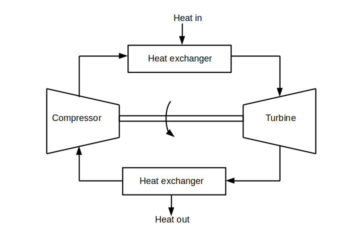
Thus, the closed Brayton cycle consists of four processes -
Isentropic compression
Heat addition at constant pressure
Isentropic expansion
Heat rejection at constant pressure.
We skip the P-V and T-S diagrams for this cycle as they are fairly simple. But we discuss in detail the efficiency that can be derived from this cycle
Efficiency of Brayton cycle
The efficiency of the Brayton cycle can be given as:

where rp is the pressure ratio and k is the specific heat ratio. Just from the glance of the equation, one can understand the efficiency of the ideal Brayton cycle under air-standard assumptions depends on only two factors - the pressure ratio and the specific heat ratio for the working fluid. Further, an increase in these parameters also increases the efficiency of the gas turbine. Simply increase the pressure ratio and get higher efficiency, so, where is the problem here?
The problem is with the turbine blades, the turbine blades should be able to withstand the high temperature and high pressure resulting out after the combustion process. The inability of the blades of turbines to withstand high temperatures limits the efficiency of the overall system.

Further, if the temperature at the inlet of the turbine is fixed to a certain value, it is observed that the work output initially increases with increasing pressure ratio, reaches a maximum and then starts decreasing drastically with further increase in pressure ratio. Thus, to derive the same power, the mass flow may have to increase which means burning more fuel and thus the complete process turning expensive. Hence, a compromising solution needs to arrive to select the pressure ratio in order to save the costs as well as the blades of the turbine. The typical pressure ratio chosen is between 12 to 16. This definitely makes room for modifying the existing Brayton cycle to derive more work output and we discuss the same in the next section.
Brayton cycle - Methods to increase the net work

Owing to their large usage in the aircraft as well as the power plants, significant research has been conducted in order to increase the work output from the Brayton cycle by applying certain modifications. One of the ways is to cast the turbine blades using Titanium, which can sustain large temperatures. But this is far expensive. We discuss the following altercations done in the cycle to increase the performance of the Brayton cycle.
Brayton cycle with a regenerator :
The exhaust gas temperature leaving the turbine is quite higher in comparison to the temperature of the air leaving the compressor. Using a heat exchanger known as a regenerator, the high temperature of the exhaust gasses can be used to heat the air leaving the compressor.
This additional heat thereby helps in reducing the heat input requirements and thereby increases the work output. However, for a very high-pressure ratio, the air leaving the compressor can be higher than the exhaust gas temperature making the regenerator work in reverse and thereby reducing the efficiency of the cycle. So, enough care should be taken to check the temperature of the air and exhaust gasses. The parameter to access the performance of the regenerator is the effectiveness. A high effectiveness regenerator thereby saves heat supply requirements (fuel) but increases the cost and weight of an additional component.
Brayton cycle with an intercooler :
As the net work output is essentially the work difference between the turbine output and the compressor input, the ways to increase the net work can be either to increase the turbine output or reduce the compressor input. The reduction in work input of compressor can be achieved using an intercooler. An intercooler compresses the air in stages and allows the air to cool in between the different stages. Thus, the compression process remains fairly isothermal in the compressor which decreases the compressor work input.
Brayton cycle with a reheater :
Similarly, the work output from the turbine can be increased by allowing the expansion process to take place in stages and allowing the reheating in between the stages. Thus the maximum temperature reached can be kept in check and the expansion process can be made nearly isothermal.
A Brayton cycle may also use all of the three methods simultaneously which may improve the work output from the cycle quite significantly. Such a cycle is called as Brayton cycle with a regenerator, intercooler, and a reheater

Jet propulsion cycle
We have already seen an application of the Brayton cycle or the gas turbine cycle is for aircraft propulsion. Owing to a higher power-to-weight ratio, easy maintenance, light and compact with higher performance characteristics, and lesser moving parts in comparison to the reciprocating engines, gas turbines are preferred widely for powering the aircraft. The gas turbines for the aircraft application work on the open cycle called the jet propulsion cycle and differ slightly in operation compared to the Brayton cycle. For the jet propulsion cycle, the gasses are expanded to the pressure where the turbine power is sufficient enough to drive the compressor. This results in a zero net work output from the jet propulsion cycle.
However, the exhaust gasses from the exit of the turbine are accelerated using a nozzle which helps to propel the aircraft. In addition, before the air enters the compressor, it passes through a diffuser where the air is decelerated thereby increasing the pressure. The aircraft propels in the direction opposite to that of accelerating fluid. This can be achieved using either a turboprop engine wherein a large mass of fluid is accelerated slightly or using a turbo-fan or turbo-jet engine where a small mass of fluid is accelerated greatly.
History
Interestingly the advent of the Brayton cycle dates back to the same era where the Otto and Diesel cycle was patented. In fact, the Brayton cycle too was designed for reciprocating engines. However, there were problems with an explosion. Although enough modifications were done to the engine, the problem of ignition flame was still unsolved. Earlier the Brayton cycle found its application in water pumps, mills, generators, and marine propulsion. The first and the second submarines worked on the Brayton engine. These submarines are still preserved in the Paterson Museum of New Jersey.
Summary
We begin with learning about the open and the closed Brayton cycle
Next, a key performance parameter - efficiency is studied in depth
Also, we discuss the methods of increasing the work output from the Brayton cycle
Towards the end, we see the application of the Brayton cycle for aircraft propulsion.
References
Cengel, Yunus A., Michael A. Boles, and Mehmet Kanoglu. Thermodynamics: an engineering approach. Vol. 5. New York: McGraw-hill, 2011.
Comments