.png)

Introduction
Image a world without traffic rules. Fun and scary right! It is always fun to not have any rules but at the same time, it becomes scary as you are not safe anymore. Similarly, GD&T is just a set of rules to follow.
What is GD&T?
GD&T is a language of symbols and standards that facilitate communication between entities working together to produce a component that is designed and used by engineers and manufacturers.
Geometric Dimensioning and Tolerancing (GD&T) can be defined as a structured language of symbols, rules, and definitions that allows the geometrical features of mechanical parts to be defined according to functional limits of imperfection.
In other words, these rules are only for controlling the quality of the component. It helps to control the dimensions and tolerances of the component, which in turn increases the production and profits of the organization.
Why is it important?
As stated above, it is very easy to convey what an engineer expects from a manufacturer. Instead, of long notes with the component drawing, some symbols are easy to make. Additionally, it clearly conveys the tolerancing of a component, which reduces errors. It is quite helpful and important for any design engineer.
Basics - Datums and True Position
Datum Reference Frame (DRF):
DRF is a three-dimensional coordinate system, with three translational and three rotational degrees of freedom. It is a frame of reference or origin to all the referenced geometric specifications. The three planes can be established as follows:
Primary Datum - minimum three points of contact
Secondary Datum - minimum two points of contact
Tertiary Datum - minimum one point of contact
Datums are points, lines, and/or planes, that finally can establish DRF.
Datum features are physical parts that are not perfect. e.g, holes, slots, etc.
True Position:
The true position of any feature is the exact coordinate, where it should actually be located. A true position of 0.020 means that the feature is off by 0.020 from where it actually should be.
GD&T Symbols
The tolerancing symbols fall into 5 groups as follows:
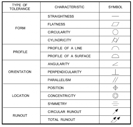
Form Controls: Specifies the shape of the feature
Surface straightness or straightness in normal form is a tolerance that controls the form of the line on a surface or feature. In axis straightness, a part's axis must be allowed some amount of curve.
On a flat surface, flatness refers to the deviation between high and low points.
Circularity defines a cross-section of a round feature and determines how close it should be to the true circle.
Similar to Circularity, Cylindricity defines close a feature should be to a true cylinder.
Profile Controls
Profile of a line is a comparison between a two-dimensional cross-section and an ideal shape, with some tolerance.
Profile of a surface is measured using CMM/gauge and compared with an ideal surface, with some tolerance.
Orientation Controls
Angularity describes the orientation of a particular feature with respect to a referenced angle
Perpendicularity can be described as a line/surface which is at 90 degrees angle with respect to the datum.
Parallelism is a tolerance that controls parallelism between two surfaces/planes.
Location Controls
Position is the location that can be used as a datum or reference.
Concentricity compares the location of a cylindrical feature with the datum axis.
Symmetry ensures that the features are similar across a datum plane for non-cylindrical parts.
Runout Controls
Circular runout is how much one feature changes with respect to a datum (start point), until it rotates 360 degrees, around the datum axis.
Total runout also considers the variation in the axial direction along with circular rotation.
Feature Control Frames
Feature control frames carry the information related to GD&T in a drawing sheet, which is divided into different compartments.
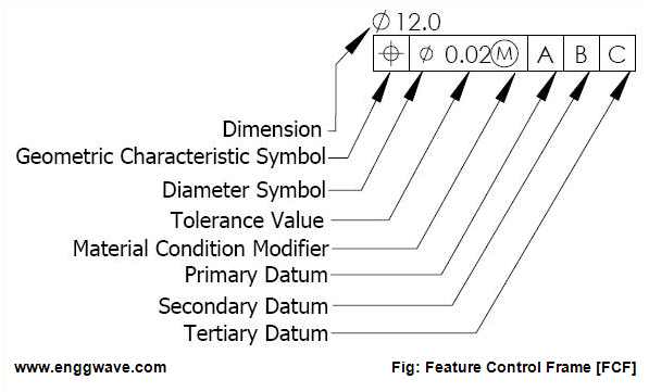
Leader arrow points to the feature that the geometric control is placed on (not shown in the image above).
Dimension is the actual/true dimension the feature is to be expected off.
Geometric Characteristic Symbol indicates the geometric control.
Diameter Symbol (situation-specific/if required) indicates a diametric tolerance specification.
Tolerance Value defines the numeric value of tolerance.
Material Condition Modifier defines the condition for not only dimension but also other geometric specifications such as weight, thickness, etc. For this specific example, it is the maximum material condition.
Primary Datum (if required) is denoted by a letter, which acts as a datum for a feature somewhere on the part corresponding to the same letter.
Secondary Datum (if required) is fixed after the primary datum and is placed right to it in the feature control frame. The corresponding letter can be found on the part somewhere.
Tertiary datum (if required) is similar to the Secondary datum and is fixed after it.
History
Stanley Parker worked at the Royal Torpedo Factory in Alexandria, West Dunbartonshire, Scotland, and was working in the production of naval weapons.
He developed the concept of "True Position" to increase production. In 1956, Parker published Drawings and Dimensions, which became the basic reference in the field.
Summary
Geometric Dimensioning and Tolerancing can be defined as a structured language of symbols, rules, and definitions that allows the geometrical features of mechanical parts to be defined according to functional limits of imperfection.
The geometric rules are only for controlling the quality of the component, which in turn increases production and hence profits.
Datum Reference Frame is a three-dimensional coordinate system, which acts as an origin or reference/datum.
Feature control frames carry the information related to GD&T in a drawing sheet, which is divided into different compartments.
Hello everyone! Hope you all had a great Easter! Also, how do you like this article? Do you think it is helpful? Let me know in the comments section below! See you soon :)
Comments